Single-Axis Solar Tracker Mounting: Structure, Drives and Site Selection
How single-axis tracker structures are engineered: torque tubes, pile spacing, drive systems, stow position and the 15-25% yield gain over fixed tilt.
TL;DR — Key Takeaways
- Category:
- Trackers
- Reading time:
- 9 min read
- Published:
- October 1, 2026
- Topics:
- solar tracker · single-axis tracker · tracker mounting structure · PV tracker system
- In short:
- How single-axis tracker structures are engineered: torque tubes, pile spacing, drive systems, stow position and the 15-25% yield gain over fixed tilt.
A single-axis tracker rotates the whole row of panels to follow the sun from east to west, typically boosting annual energy yield by 15–25% over a fixed-tilt array. In high-irradiance regions such as the Middle East, that gain is often worth more than the added structure cost. This article covers how tracker mounting structures are engineered and what buyers must specify.
How a single-axis tracker is built
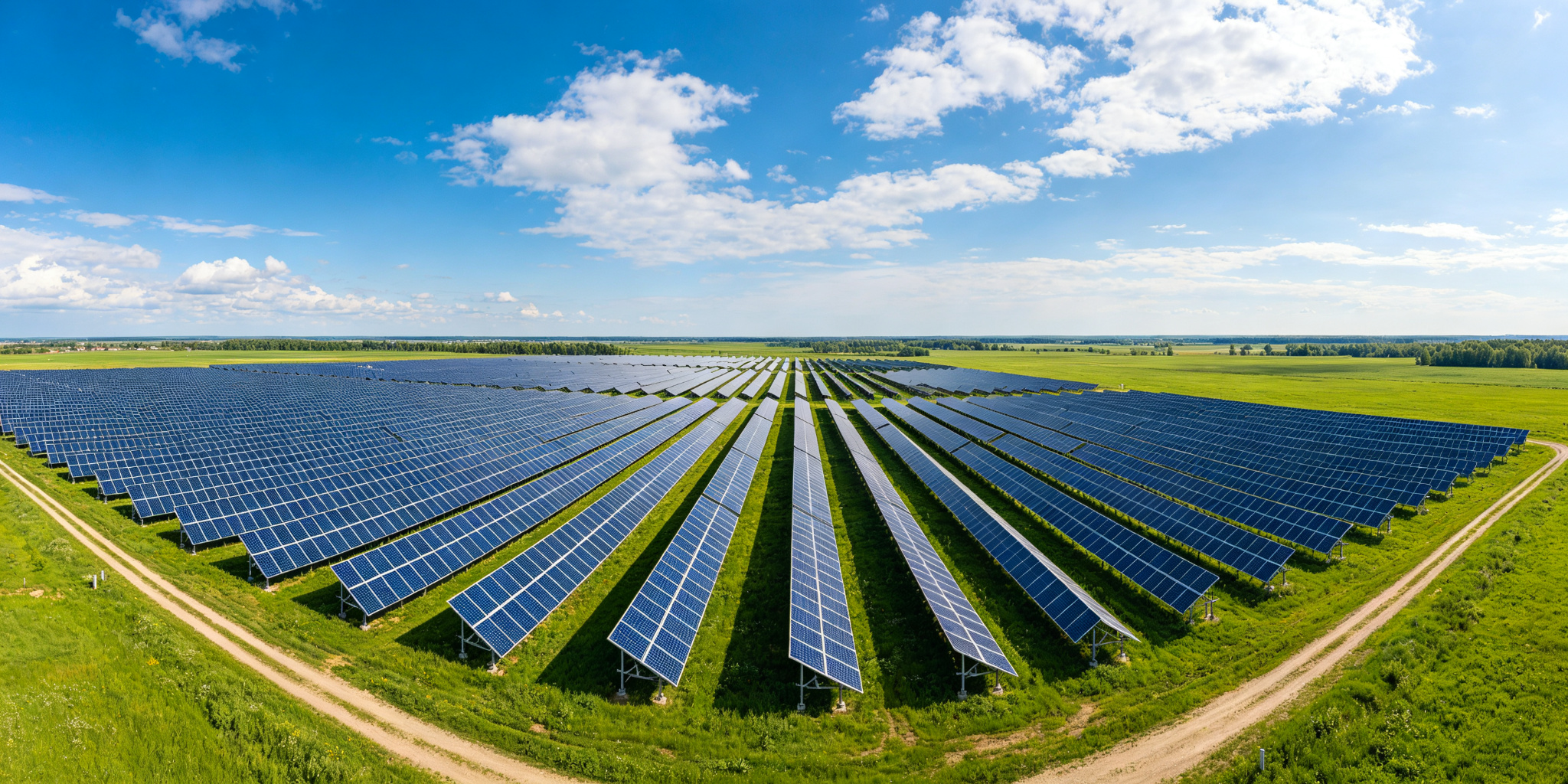
A tracker row is a long rotating beam — the torque tube — supported on pile foundations, with panels mounted on rails attached to the tube. A drive unit at one end (or at intermediate posts for long rows) rotates the tube through the day. The three load paths are: panels to rails, rails to torque tube, torque tube through bearings to piles.
Core structural components
- ▸Torque tube: the main rotating member, typically 2.5–6 m long sections of round or square HDG steel tube, connected with flanges or bolted splices.
- ▸Piles and posts: driven steel piles with a bearing/hub assembly that lets the tube rotate; typical post spacing 30–60 m per drive section.
- ▸Bearings: plain or rolling bearings mounted on posts, transferring vertical load while allowing rotation.
- ▸Drive system: slewing drive or linear actuator with a controller and wind sensor.
- ▸Module rails and clamps: mounting channels fixed to the torque tube at the specified panel orientation.
Engineering parameters (2026)
| Parameter | Typical value | Why it matters |
|---|---|---|
| Tracking range | ±45° to ±60° | Wider range = more morning/evening capture |
| Post spacing | 30–60 m per drive | Sets drive torque and tube stiffness |
| Torque tube size | Ø76–168 mm (round) or 100–200 mm (square) | Driven by row length and wind load |
| Design wind | Up to 60 m/s | Stow position is the critical protection |
| Snow load | Up to 1.5 kN/m² | Stow angle must shed snow |
| Operating temperature | −40°C to +85°C | Drives lubricant and controller spec |
| Design life | 25 years | HDG 85 μm coating per ISO 1461 |
Wind stow: the design that protects the whole plant
Trackers fail in wind when they stay flat instead of stowing. On high-wind alarms the controller rotates every row to the stow angle (typically 0–10° from horizontal, into the wind), drastically reducing the lift area. The structural design must confirm that both the parked position and the stow position survive the 60 m/s design wind, and that the drive can hold the row against the resulting moment. This is the single most important difference between a tracker and a fixed mount.
Drive systems compared
| Drive type | Typical use | Trade-off |
|---|---|---|
| Slewing drive | Utility-scale rows up to 90 m | High torque capacity, simple alignment, medium cost |
| Linear actuator | Short rows and smaller arrays | Low cost, but higher maintenance over 25 years |
| Hydraulic | Very long rows / special sites | High force, but pump and seal maintenance |
Yield gain: what the 15–25% actually depends on
The gain from tracking depends on latitude and climate. In sun-belt regions (latitudes 20–35°) with clear skies, the annual gain over fixed tilt typically reaches 20–30%; in cloudy northern climates it drops below 15%. Bifacial modules amplify the benefit because the row keeps more diffuse light reaching the rear side. Before paying the tracker premium, ask your developer for a site-specific irradiance simulation — the same tracker that earns 25% in Riyadh may earn only 12% in a cloudy coastal market.
Cost and reliability reality
A tracker structure costs roughly 20–40% more per watt than fixed-tilt racking because of drives, controllers and extra moving parts. That premium pays back when the yield gain exceeds the cost delta — which it does in high-DNI markets. Reliability is the hidden variable: moving parts fail, so buyers should check the drive warranty (typical: 5–10 years with a 25-year design life), the availability of spare drives, and whether the supplier’s torque-tube splices are field-proven.
Buyer checklist for tracker structures
- ▸Stow strategy: wind speed threshold, stow angle, and recovery procedure documented
- ▸Torque tube and splice design verified for the specific row length
- ▸Drive torque margin above worst-case wind moment
- ▸Backup control: manual or battery-powered stow if grid power drops
- ▸HDG 85 μm coating on all structural steel with certificates
- ▸Spare drive and bearing kit included in the supply scope
Sourcing trackers that match your site
HAOQIN supplies single-axis tracker structures and components — torque tubes, posts, bearings and mounting rails — in certified Q355B galvanized steel, engineered for 60 m/s wind, 1.5 kN/m² snow and −40°C to +85°C operating range, with export documentation for utility-scale projects. Send your row layout and site wind data for a structural review and quotation.
Need a structure engineered for your site?
Send us your project details for load calculations, configuration and pricing.